PUS Services
Overview
This section describes how to request creation and handle processing of the telemetry (TM) and telecommands (TC) in the PUSopen®. PUSopen® implements the following ECSS PUS services:
PUS Service 1 - Request Verification (PUS 1 (Request Verification))
PUS Service 3 - Housekeeping (PUS 3 (Housekeeping))
PUS Service 5 - Event Reporting (PUS 5 (Event Reporting))
PUS Service 8 - Function Management (PUS 8 (Function Management))
PUS Service 13 - Large Packet Transfer (PUS 13 (Large Packet Transfer))
PUS Service 17 - Test (PUS 17 (Test))
PUS Service 20 - Parameter Management
Common PUS User (PUS User)
PUS Services form the top-most part of the PUSopen® stack. Each PUS Service provides a set of APIs to control its operation (e.g., to produce TM or TC) and to retrieve received data. Each service contains a set of observable parameters, which can be read by the user application code. See Section 4.8 for more details.
PUS Service Model
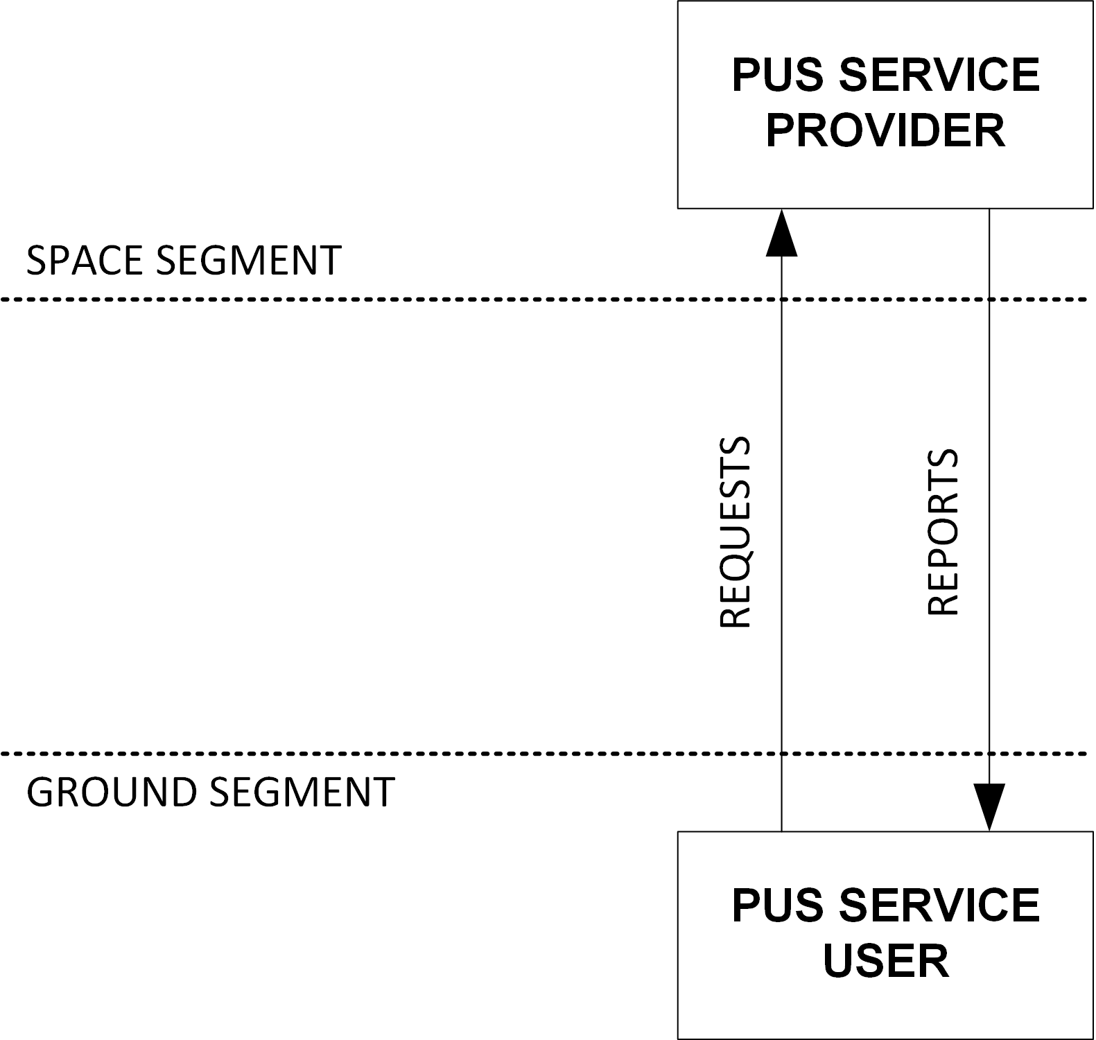
A PUS service is composed of the service provider and service user, forming two endpoints of communication (Figure 11). Typically, a service user and provider are deployed on different systems or subsystems located on the Space or Ground Segments. Communication may start at any of the two endpoints.

Fig. 12 ECSS PUS Service Model
For example, PUS service 17 (Are-you-alive test) requires the service user to generate TC[17,1] and send it to the service provider. Provider receives TC[17,1] and, in response, generates TM[17,2], meaning “Yes, I’m alive”.
Service 3 is an example of one-way communication. The PUS service 3 provider collects telemetry at configured intervals and sends it in TM[3,25] to the service User.
The following sections describe the communication sequence between the service user and provider for each implemented PUS service. The produced TC and TM structure is configurable and compatible with ECSS standards.
Implementation Notes
Only selected TM and TC of the listed PUS services are implemented by the PUSopen®. Implemented parts of the services comply with ECSS PUS standard. The following sections list TMs and TCs implemented for each PUS service and the sequence of their transmission. Code examples are provided for each PUS service.
PUS 1 (Request Verification)
PUS Service 1 is the main distribution point of the received TM/TCs. Each TC contains identification of its destination service provider. If the service provider for the received TC exists, the PUS 1 provider forwards the TC to the destination service provider.
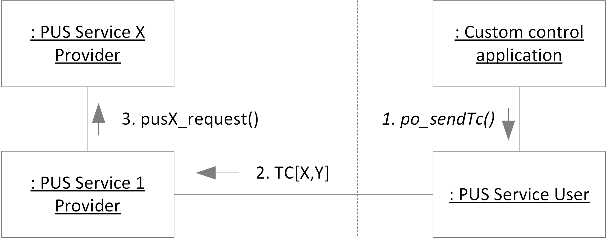
Figure PUS 1 communication sequence shows the communication sequence of the PUS 1 telecommand sending. The dotted vertical line in the middle of the figure separates two communicating instances of the PUSopen® stack. Typically, the PUSopen® instance on the right of the Figure 12 is located on the Ground Segment, and the instance on the left is deployed on the Space Segment (i.e., satellite).

Fig. 13 PUS 1 communication sequence
PUS 1 Telemetry Reports
Optionally, user application code may request TM[1,X] reports on the acceptance, start of execution, progress, and completion of a telecommand (Table 9). The request for the TM[1,X] report is done via acknowledge (ACK) flags of the PUS TC header (see Listing 11).
Report |
Description |
|---|---|
TM[1,1] |
Successful acceptance verification report. Send automatically by PUS 1 service provider if the bit 3 (TC_ACK_ACCEPTANCE) of the TC acknowledgment flags is set. |
TM[1,2] |
Failed acceptance verification report. Send automatically by PUS 1 service provider, independently of the bits set in the ACK field of the TC. The TC verification fails if:
|
TM[1,3] |
Successful start of execution. Send automatically by the ECSS-defined PUS service providers if the bit 2 (TC_ACK_START) of the TC acknowledgment flags is set. Custom PUS services may send the TM[1,3] using API pus1tm_3_start_ok(). |
TM[1,4] |
Failed start of execution report. Send automatically by the ECSS-defined PUS service providers, independently of the bits set in the ACK field of the TC (Table 10). Custom PUS services may send the TM[1,4] using API pus1tm_4_start_fail(). |
TM[1,5] |
Successful progress of execution report. Send automatically by the ECSS-defined PUS service providers if the bit 1 (TC_ACK_PROGRESS) of the TC acknowledgment flags is set. Custom PUS services may send the TM[1,5] using API pus1tm_5_progress_ok(). |
TM[1,6] |
Failed progress of execution report. Send automatically by the ECSS-defined PUS service providers, independently of the bits set in the ACK field of the TC (Table 10). Custom PUS services may send the TM[1,6] using API pus1tm_6_progress_fail(). |
TM[1,7] |
Successful completion of execution report. Send automatically by the ECSS-defined PUS service providers if the bit 0 (TC_ACK_COMPLETION) of the TC acknowledgment flags is set. Custom PUS services may send the TM[1,7] using API pus1tm_7_completion_ok(). |
TM[1,8] |
Failed completion of execution report. Send automatically by the ECSS-defined PUS service providers, independently of the bits set in the ACK field of the TC (Table 10). Custom PUS services may send the TM[1,8] using API pus1tm_8_completion_fail(). |
Table 10 describes behavior of the ECSS-defined PUS service providers with respect to the TM[1,x] reports.
PUS Service |
TM[1,X] Reporting Behavior |
|---|---|
PUS 1 PUS 2 |
Reports created automatically (Table 9). |
PUS 3 |
TM[1,3] is sent if:
otherwise TM[1,4] is sent. TC[1,7] is generated after enabling (TC[3,5]) or disabling (TC[3,6]) PUS 3 report generation if:
|
PUS 5 |
No TCs specified by the PUS standard |
PUS 8 |
TM[1,3] is sent if:
otherwise TM[1,4] is sent. TC[1,7] is generated after exit from User function:
otherwise TM[1,8] is sent. |
PUS 13 |
No TCs specified by the PUS standard |
PUS 17 |
TM[1,3] is sent if:
otherwise TM[1,4] is sent. TC[1,7] is generated after exit from User function:
otherwise TM[1,8] is sent. |
PUS 20 |
TM[1,3] is sent if:
otherwise TM[1,4] is sent. TC[1,7] is generated after exit from User function:
otherwise TM[1,8] is sent. |
TC Acknowledgment Flags
PUSopen® user application code may set the following TC acknowledgment flags:
Flag |
Bit of TC ACK field |
Description |
|---|---|---|
TC_ACK_ACCEPTANCE |
3 |
Request TM[1,1] Successful acceptance verification report |
TC_ACK_START |
2 |
Request TM[1,3] Successful start of execution report |
TC_ACK_PROGRESS |
1 |
Request TM[1,5] Successful progress of execution report |
TC_ACK_COMPLETION |
0 |
Request TM[1,7] Successful completion of execution verification report |
The following code shows how to request the TM[1,X] acceptance and execution reports when sending a TC.
uint8_t buf[512] = { 0 };
uint16_t len = 0;
uint8_t payload[2] = { 1, 2 };

/* TC acknowledgment flags */
uint8_t ack_flags = TC_ACK_ACCEPTANCE | TC_ACK_START | TC_ACK_COMPLETION;

/* Create TC[17,1] with ACK flags set */
po_sendTc(17, 1, ack_flags, payload, 2, 1, 0);

/* Get the byte stream and send using function */
po_frame(buf, &len);
send(conn, buf, len);
TM[1,X] Custom Data
The TM[1,2], TM[1,4], TM[1,5], TM[1,6], and TM[1,8] allow for custom data to be attached the telemetry report. PUSopen® provides a custom callback po_tm1x that (if defined and set) allows user to specify the custom data attached to the report.
Note: The custom callback function po_tm1x is only invoked for the TM[1,2], TM[1,4], TM[1,5], TM[1,6], and TM[1,8]. All other TM[1,x] do not allow custom data in the report (see ECSS-E-ST-70-41C).
Listing 12 shows how to attach any custom-formatted data to the TM[1,x] reports. The custom callback po_tm1x() in the example will be invoked every time a TM[1,x] report that allows custom data in its payload is produced.
#include <pusopen/pusopen.h>

/* Custom callback for adding custom data to the TM[1,X] reports */
po_result_t po_tm1x(void *conf, po_pus1_cb_t *cb)
{
    (void)conf;

    /* Attach custom data to TM[1,x] report */
    cb->usr_data[0] = cb->result_code;
    cb->usr_data[1] = cb->tc->service;
    cb->usr_data[2] = cb->tc->subservice;
    *cb->usr_data_len = 3;

    return PO_SUCCESS;
}

int main()
{
    /* Configuring PUSopen */
    po_init();
    po_set_apid(1);
    po_set_apuid(2);
    po_set_fess_instance(0, &fess0);
    po_set_callback_pus1tm(po_tm1x);
}
PUS 3 (Housekeeping)
PUS Service 3 provider implements data collection and reporting (also termed as “Housekeeping” information or “HK”). The user configures HKs and TM[3,25] data reports in the PUSopen® configuration (Section 3).
At runtime, the user application periodically triggers the PUS 3 provider (API po_triggerPus3 ()). After the configured number of trigger calls to pus3_trigger (), the PUS 3 provider collects the configured HKs and sends them in one TM[3,25] report.
In the following code example, a PUS 3 report TM[3,25] is configured in the PUSopen® configuration with an interval of 3. The PUS 3 provider is periodically triggered in every iteration of the “while” loop. On the third call of po_triggerPus3 (), a TM[3,25] report is assembled and retrieved via po_frame ().
uint8_t index = 1;
uint8_t buf[128] = { 0 };
uint_16_t len = 0;
po_result_t res;

while (1) {
    res = po_triggerPus3();   /* Trigger PUS 3 provider */

    if (res == PO_SUCCESS) {
        po_frame (buf, &len);
        send(buf, len);       /* User-defined "send" function */
    }
    index++;
}
PUS 5 (Event Reporting)
Event Reporting Service PUS 5 allows users to create and send TM[5,x] onboard event notification reports. In practice, events report findings like out-of-range data, data thresholds met, detected HW errors, etc.
The PUSopen® configuration defines onboard events. Each event is identified by its ID, criticality level, and associated data length.
ECSS and PUSopen® recognize four levels of the PUS 5 events:
Level |
C Enum value |
Report |
Description |
|---|---|---|---|
Info |
PUS5_EVT_INFO |
TM[5,1] |
Informational event |
Low |
PUS5_EVT_LOW |
TM[5,2] |
Low-criticality event |
Medium |
PUS5_EVT_MEDIUM |
TM[5,3] |
Medium-criticality event |
High |
PUS5_EVT_HIGH |
TM[5,4] |
High-criticality event |
The user application may send TM[5,x] event using the API po_pus5tm (). The following code example shows how to send TM[5,x] event reports defined in the PUSopen® configuration with ID “1”, level “Info,” and four bytes of associated data.
#include <pusopen/pusopen.h>

uint8_t data[4] = { 1, 2, 3, 4 };

po_pus5tm( 1U,            // event ID from PUSopen\ :supsub:`reg` configuration
           data,          // event data (length in Mission DB)
           50);           // destination APID of the TM[5,x]
PUS 8 (Function Management)
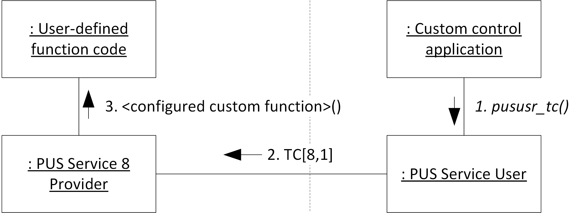
PUS 8 provider is used to trigger user-defined application functions (Figure 14). A PUS 8 user (typically a Ground Control) sends a telecommand TC[8,1] with the user function ID. Once the TC[8,1] reaches the PUS 8 provider (typically onboard), the user function identified in the TC is called by the PUSopen® stack.

Fig. 14 PUS 8 Command Flow
User functions are defined in the PUSopen® configuration and contain unique ID and address of the user function to be called. User function must have the following prototype:
po_result_t <function name> (uint8_t fid, uint8_t *data, uint16_t len)
where:
Parameter |
Type |
Description |
|---|---|---|
fid |
uint8_t |
Function ID (from PUSopen® configuration) |
data |
uint8_t* |
Data to be passed into function (pointer) |
len |
uint16_t |
Length of data to be passed |
The return value of the user-defined function is reserved for future releases of PUSopen®.
PUS 8 doesn’t have any other public APIs. The only way to trigger PUS 8 is via TC[8,1]. See code examples distributed with PUSopen®.
PUS 13 (Large Packet Transfer)
Service 13 provides functionality for uplink and downlink of large data sets.
One uplink and one downlink are allowed at the time. PUSopen® currently doesn’t allow multiple parallel uplinks and multiple parallel downlinks. Requests for more than one parallel downlink will be rejected by the PUSopen®.
The user application initiates a large data downlink by calling po_pus13Downlink (). Once triggered, the downlink sequence is driven by the user application’s periodic call to the API po_triggerPus13 (). This way, the user application controls the rate at which packets with parts of the large data set are produced and stored for transmission.
A data set is downlinked in a sequence of one TM[13,1] (the initial part of the data set), several TM[13,2] with intermediate parts of the data set and the final TM[13,3] with the remaining part of the data set. TM[13,1] and TM[13,3] are mandatory in every downlink sequence.
PUSopen® configuration allows the user to specify the size of a single downlinked part of a data set (data payload of one TM[13,x] report). As stated above, the user application controls the rate at which the PUS 13 produces the TM[13,x] reports from the ongoing downlink.
#include <pusopen/pusopen.h>

uint8_t dataset[2048] = { 0 };  // data set for downlink

uint8_t buffer[512] = { 0 };    // buffer for created TM[13,x]
uint16_t len = 0;               // packet length
uint16_t seq;                   // downlink sequence id

po_pus13Downlink( 50,           // destination APID for downlink
                dataset,      // data set for downlink
                2048);        // size of the data set


while (1) {                     // main system loop
    if ( po_pus13isDownlink() ) {
        po_triggerPus13();      // generate another TM[13,x]
    }

    po_frame(buffer, &len);     // retrieve next created TM[13,x]
    send(buffer, len);          // user-defined "send" function
}
A large data uplink is initiated by the call to po_pus13Uplink (). Once triggered, the downlink sequence is driven by the user application’s periodic call to the API po_triggerPus13 (). This way, the user application controls the rate at which packets containing parts of the large data set are produced and stored for transmission.
Uplinked data are split into a series of TC[13,9] (initial part), zero or more TC[13,10], and one TC[13,11].
#include <pusopen/pusopen.h>

uint8_t dataset[2048] = { 0 };  // data set for uplink

uint8_t buffer[512] = { 0 };    // buffer for created TC[13,x]
uint16_t len = 0;               // packet length
uint16_t seq;                   // uplink sequence id

po_pus13Uplink( 50,           // destination APID for downlink
                dataset,      // data set for downlink
                2048,         // size of the data set
                &seq);        // returned sequence id


while (1) {                     // main system loop
    if ( po_pus13IsUplink() ) {
        po_triggerPus13();      // generate another TC[13,x]
    }

    po_frame(buffer, &len);     // retrieve next created TC[13,x]
    send(buffer, len);          // user-defined "send" function
}
On the receiving side, the received TCs can be consumed by the user code inside the customer-implemented callback function po_tm () and po_tc () - See Section 3.5.
PUS 17 (Test)
PUS 17 implements the “Are you alive” request for the target subsystem. In network jargon, this method of checking system status is called the “ping.”
Application code may call PUS service user (Section 5.10) to generate TC[17,1], which is answered by the PUS 17 provider in TM[17,2] “I-am-alive” report. Alternatively, the PUS user may generate TC[17,3], answered by the TM[17,4] with the attached APID in the TM report data section.
PUS 17 provider doesn’t expose any public APIs. PUS service user (Section 5.10) may be used by the application code to generate TC[17,1] or TC[17,3].
#include <pusopen/pusopen.h>

uint8_t payload;

res = po_sendTc( 17U, 1U,         //  TC[17,1]
                 &payload, 0U,    //  no payload
                 50U);            //  destination APID
PUS User
PUS User is a generic module capable of sending any desired TC[x,y] via API po_sendTc () or TM[x,y] via po_sendTm (). PUSopen® forwards all received TM/TCs to the custom callback functions po_tm() and po_tc (Section 3.5).
In the example below, a PUS Service User is called to generate TC[8,1] (calling custom-defined on-board function; see Section 5.7). The TC[8,1] ‘s payload is one byte that identifies a called function.
#include <pusopen/pusopen.h>

uint8_t fid = 5;                 /* PUS 8 function ID = 5 */

res = po_sendTc( 8, 1,           /* TC[8,1] */
                 &fid, 1,        /* 1 byte payload */
                 50U);           /* Destination APID */
The response to the TC or as a part of generated telemetry, a subsystem may receive TM reports. Each received TM report is forwarded to the custom-defined callback function po_tm(). There is one call to the pususr_tm() for each TM received. The same applies to all received TC and custom callback function po_tc().
#include <pusopen/pusopen.h>

po_result_t po_tm(po_tmdesc_t * tm)
{
    if (( tm->service == 17 ) && ( tm->subservice == 2 ))
        print(" TM[17, 2] - Subsystem is alive.\n ");

    return PO_SUCCESS;
}
Custom PUS services
The ECSS PUS-C standard defines 23 basic PUS services. ECSS services use service IDs lower than 128. All PUS services with service IDs equal to or higher than 128 are custom-defined.
PUSopen® allows adding and calling custom PUS services via custom-defined callback po_tc ().
#include "pusopen.h"

po_result_t po_tc (po_tcdesc_t * tc) {

    if ( tc->service == 129 ) {
        Pus129handler(tc);     // Custom-defined handler
    }

    return PO_SUCCESS;
}