PUSopen® Overview
Overview
PUSopen® is the ECSS PUS and CCSDS-compliant software communication stack with associated resources (guides, help, and tutorials). PUSopen® implements selected ECSS PUS services, CCSDS Space Packets, Packet Routing, Virtual Channels, and serial packet encoding. In addition, the AES-128 encryption is provided to secure the transmission, a common requirement in modern communication systems.
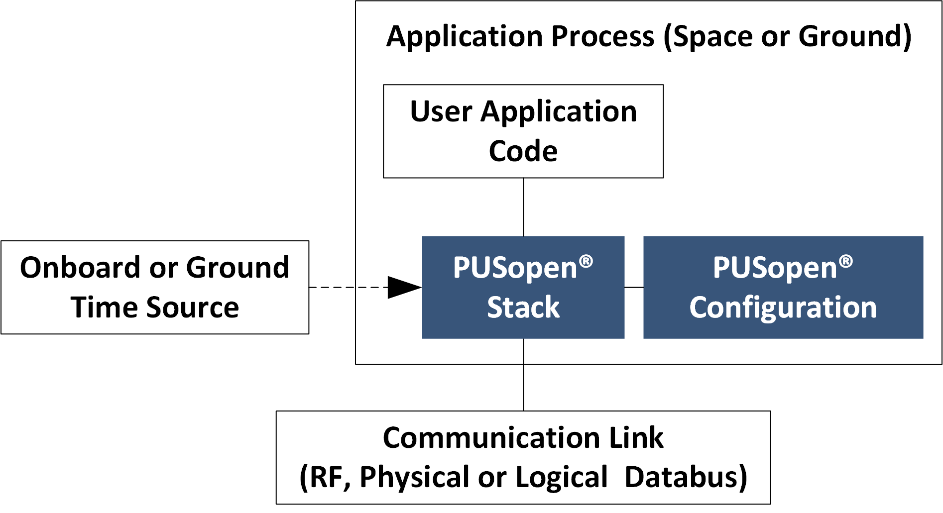
Fig. 3 PUSopen® Context
The PUSopen® product is scalable and fits medium and large satellite payloads and systems with low processing and memory resources, such as microcontrollers commonly used in small satellites. The user can configure the size of the internal buffers (to control the final memory footprint) and the pace of the stack operations.
The PUSopen® stack is configurable via its header files. A set of custom hook functions allows the user to implement application-specific behavior (e.g., retrieval of onboard time for telemetry time stamp).
Protocols and Layers
PUSopen® stack is composed of five layers (Fig. 4) with strict downward dependency. ECSS PUS Services form the topmost layer of the stack. The PUS services send, receive, and process ECSS PUS-standardized and custom-defined telemetry (TM) and telecommands (TC).
The second layer, Packet Service (PS), wraps the PUS TM/TC into CCSDS Space Packets for transport through the network. The Packet Service layer contains mechanisms for rejecting packets if the APID indicated by the CCSDS Space Packet header is not equal to the APID of the actual Application Process.
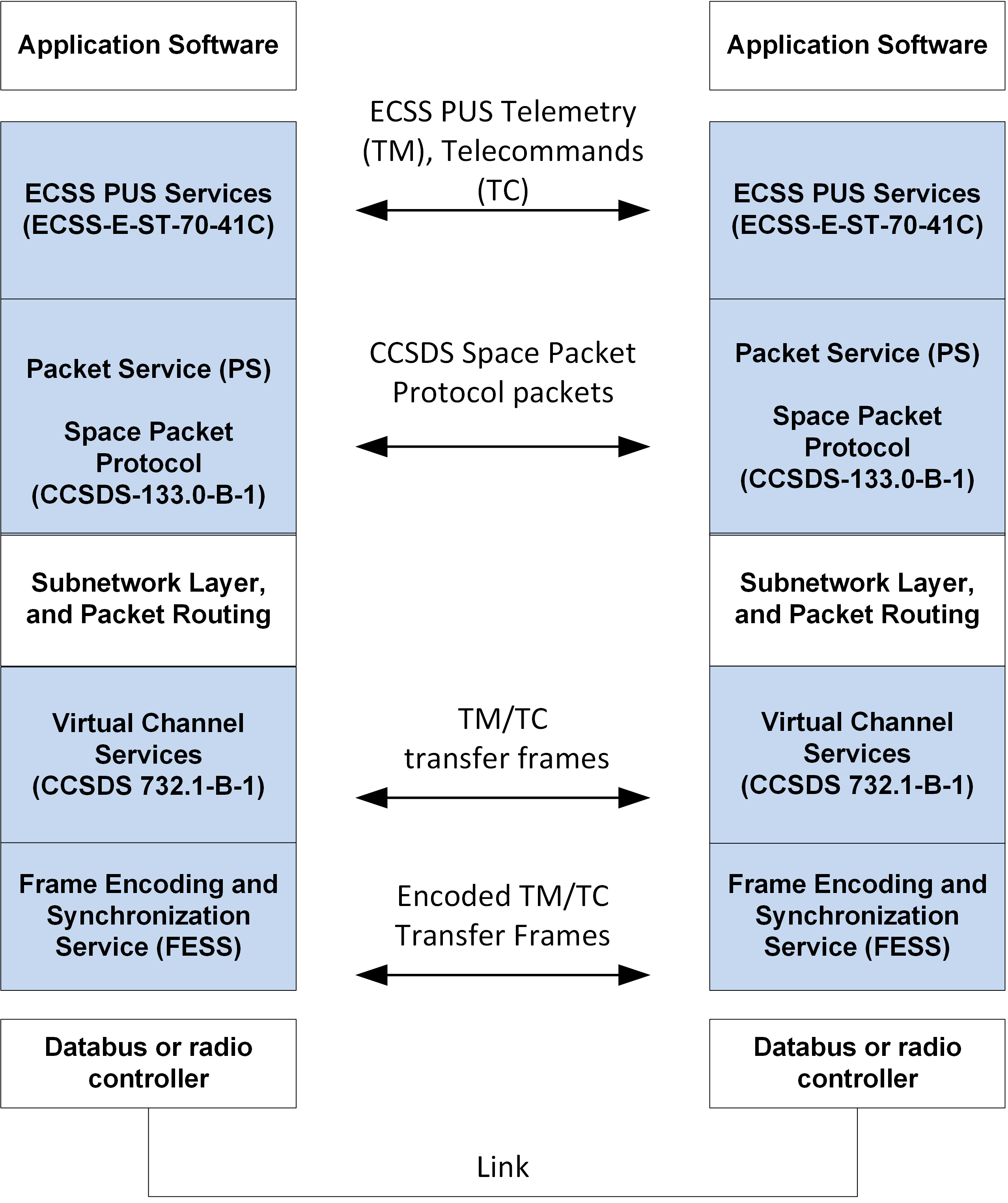
Fig. 4 PUSopen® Layers and Protocols
The Subnetwork (or “Subnet”) Layer allows users to customize the distribution of the packets through the onboard network. In the Subnetwork Layer, the user can call the CCSDS Packet Routing APIs of PUSopen® to forward the packets to different databuses or logical (software) links, based on their type (TM/TC), APID, and APUID. Template implementations of the Subnet Layer are provided with the installation of the PUSopen® stack. See Subnetwork Layer for details about the Subnet Layer.
Virtual Channel Services form the fourth, optional, layer of the PUSopen® stack. Virtual Channels are CCSDS-defined mechanisms for logical separation and prioritization of the transmitted packets wrapped into CCSDS transfer frames.
PUSopen® implements the latest specification of the CCSDS USLP transfer frames. Unlike previous specifications of the frames, the USLP frames unify the format of the telemetry and telecommand frame types. The total number, the size of Virtual Channels, and the priority of their content are configurable by the user in the PUSopen® configuration (see Configuration and Build).
The bottom-most layer of the stack is the Frame Encoding and Synchronization Layer (FESS). The FESS layer implements serial encoding and encryption of the frames (or packets if Virtual Channel Services are not used). The process of serial encoding wraps CCSDS Space Packets or Transfer Frames into HDLC or SLIP frames. Optionally, no serial encoding, or use of the Attached Synchronization marker (ASM) can be configured by the user. This is to recognize the beginning and end of a single packet in the serial byte stream. The user may optionally instantiate FESS multiple times to connect PUSopen® to multiple data buses - a common scenario in satellite payloads.
Note
Virtual Channel Services are an optional layer. If not used, the packets created by the Packet Service are forwarded directly from the Subnet Layer into the FESS layer.
The PUS and Packet Services (PS) layers form the upper part of the stack. Virtual Channels and FESS form the lower part of the stack (Fig. 4). The Subnet Layer serves as a bridge between the upper and lower parts.
Release Folders
The product is distributed as a ZIP (compressed) file. The release contains full PUSopen® source code, header files, documentation, examples, and Python and C# wrappers.
List of folders in the PUSopen® release:
Folder/File |
Description |
|---|---|
examples |
PUSopen® example application, and Python/C# wrappers. |
h |
Common PUSopen® header files. |
libfess |
Serial byte stream encoding and synchronization (HDLC, SLIP, ECSS, ASM, or no encoding). |
libpus01 |
ECSS PUS 1 service implementation. |
libpus03 |
ECSS PUS 3 service implementation. |
libpus05 |
ECSS PUS 5 service implementation. |
libpus08 |
ECSS PUS 8 service implementation. |
libpus13 |
ECSS PUS 13 service implementation. |
libpus17 |
ECSS PUS 17 service implementation. |
libpus20 |
ECSS PUS 20 service implementation. |
libpususr |
ECSS PUS User implementation, sending and receiving arbitrary PUS packets (any service/sub-service/APUID). |
libutil |
PUSopen® utility functions - mostly internal functionality (not public APIs). |
libps |
CCSDS Space Packet service (sending and reception). |
libvc |
CCSDS Virtual Channels implementation. |
test |
Test code (incl. PUSopen® Integration Test Suite). |
CMakeList.txt |
CMake system root build script for PUSopen® |
makefile |
Plain makefile for building PUSopen® |
README.md |
Overview, setting the environment, build process. |
setenv.sh (.bat) |
Scripts for setting the environment variables before the build. See README.md. |
Deployment Patterns
Section 2.2 divided layers of the PUSopen® stack into the upper part and the lower part (Figure 3). Both PUSopen® parts are provided in a single static or dynamic) library.
The upper part of the stack serves as the first interaction layer with custom application code. It creates and processes PUS TM/TC and wraps them into CCSDS packets.
The Lower part of the stack groups packets into serial frames (HDLC, SLIP, ASM) for more efficient communication over serial-like RF links or databus.
Figure 4 to Figure 7 show four recommended deployment patterns. For simplicity, the Virtual Channel Services (see Section 2.2) are omitted. The text below the figures describes each of the deployment patterns.
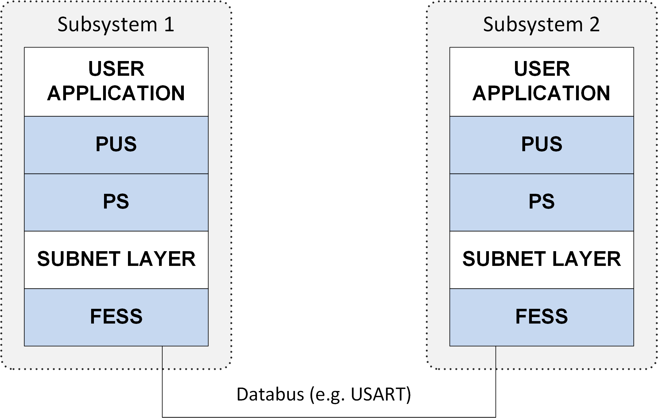
Fig. 5 PUSopen® PUSopen® Deployment pattern A
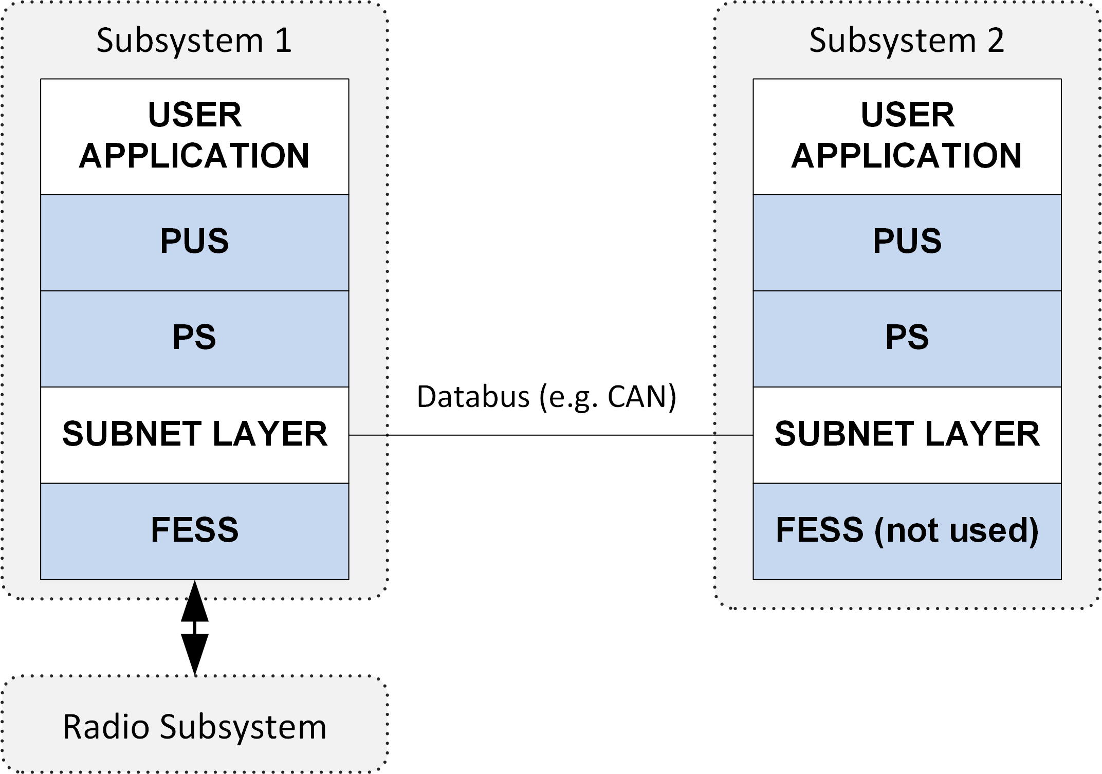
Fig. 6 PUSopen® PUSopen® Deployment pattern B
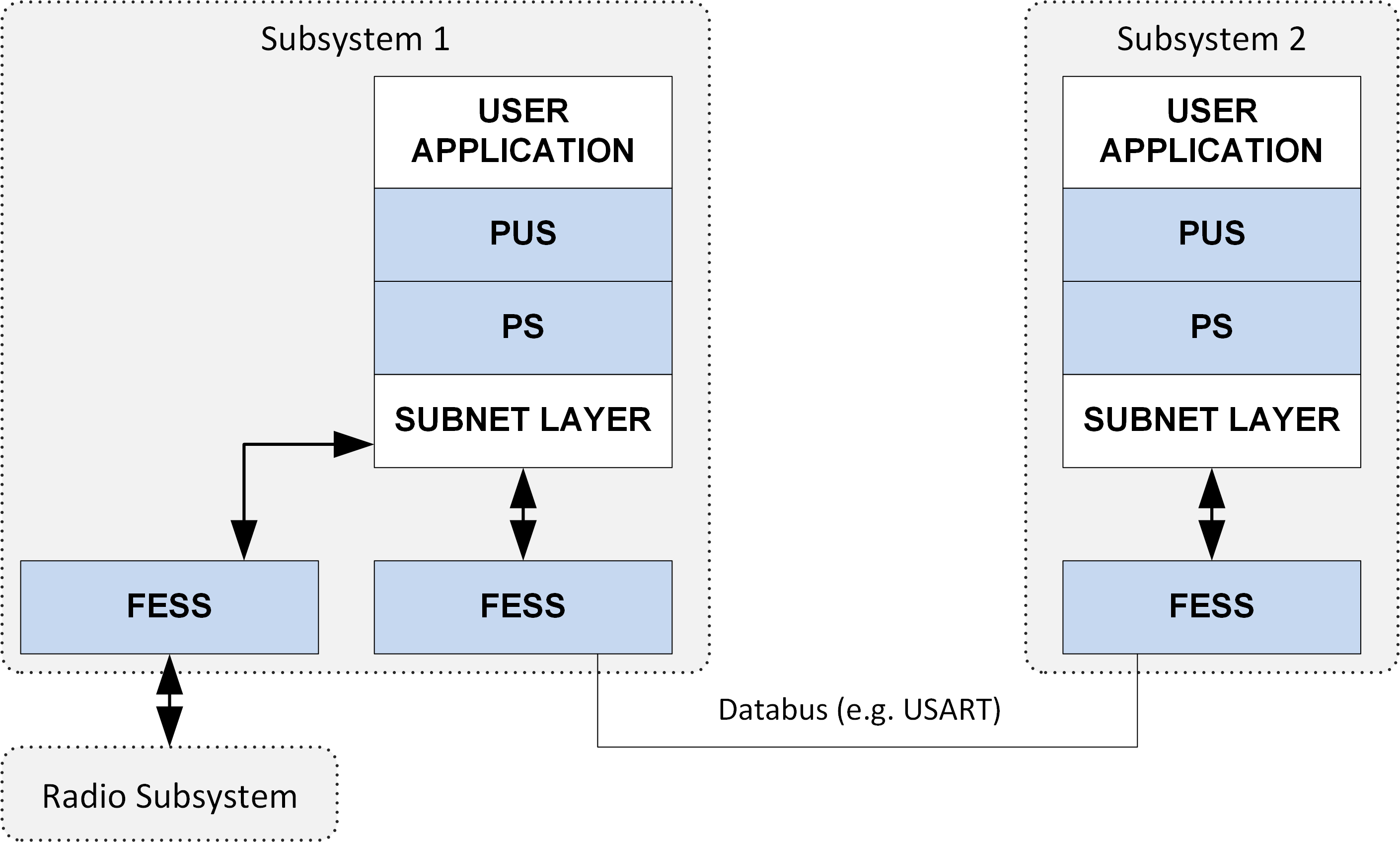
Fig. 7 PUSopen® PUSopen® Deployment pattern C
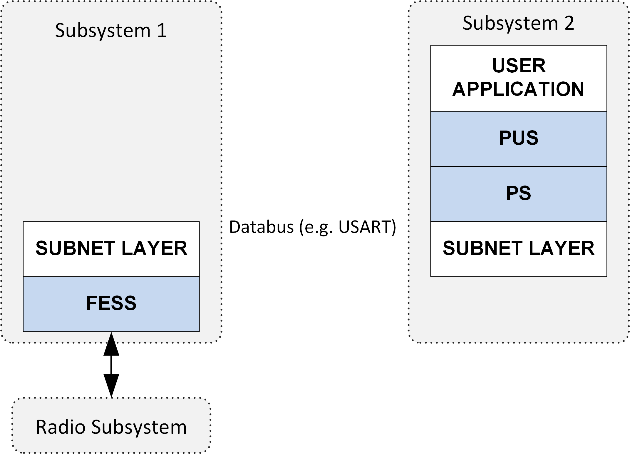
Fig. 8 PUSopen® PUSopen® Deployment pattern D
Deployment pattern A shows a typical deployment for two onboard subsystems. The FESS layer provides packet-delimiting service during serial transmission.
Deployment pattern B is a variation of pattern A; however, in this case, the FESS layer of subsystem A is used to capture packets (or frames) to and from the Radio module, while the Subnet Layer is used for communication between subsystems 1 and 2.
Deployment pattern C assumes serial communication using multiple instances of the FESS layer. One instance of FESS is used for communication between subsystems 1 and 2. The second FESS instance (created in the user application code) is used for communication with the Radio module. The user may create as many instances of FESS as necessary. The user adjusts the subnet layer to poll for packets coming from both FESS instances and forwards packets to the PS and PUS layers.
Deployment pattern D is an example of the split deployment of the upper and lower part of the PUSopen® stack. This scenario is useful for payload Packet Routing (Subsystem 1) to multiple endpoints (e.g., multiple onboard cameras).
As mentioned at the beginning of this section, the deployment patterns A to D may be combined to create the desired target architecture. Figure 8 provides an example combination of the deployment patterns A, B, C, and D.
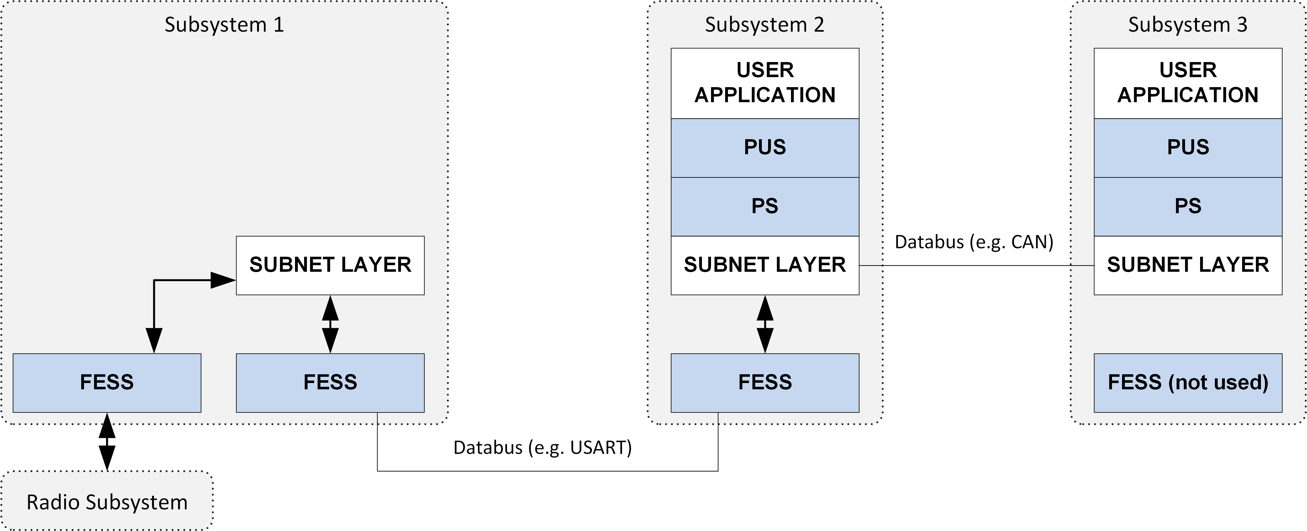
Fig. 9 PUSopen® PUSopen® Combined Deployment Scenario
Subsystems Addressing
The CCSDS Space Packets, Transfer Frames, and ECSS PUS implemented in the PUSopen® provide addressing capability for onboard and Ground systems. All data units (packets) produced and transferred by the stack are marked with the address of their destination subsystem. The stack layers identify the destination address in the transmitted packets and frames and either accept them or forward them further via the Subnet Layer.
As per ECSS and CCSDS standards, each subsystem is identified by the Application Process ID (APID) and Application Process User ID (APUID). These two identifiers don’t need to be different for a given subsystem; however, they shall be unique across the system.
Multi-tasking Env.
PUSopen® stack is designed to be deployed under both the single-task and multi-task environment.
The PUS Layer of the PUSopen® shall be called by a single task from the user application code. The PUSopen® is Operating System-independent, so its APIs are not thread-safe.
Warning
The APIs of the PUSopen® stack are not thread-safe.
The bottom part of the PUSopen® stack (multiple FESS) layers can be called from separate threads. For example, each connected data bus may be polled by a separate thread, operating the corresponding FESS instance for sending and receiving.
The send and receive buffers inside FESS instances are implemented as ring buffers, so having the reader (e.g., user application logic processing the PUS packets) and writer (e.g., CAN or UART databus driver) in the separate threads is fine.
Full Static Allocation
All buffers and instances of layers in the PUSopen® are statically allocated. There is no “malloc” call in the PUSopen®. Users must configure buffer sizes and space for standard items like reports and events at build time. An additional empty space may be configured at build time for the items (HKs, reports, events) configured at run-time (e.g., from a configuration file). See Section 3 for details.
Security
A common requirement for modern systems is to secure transmitted data. PUSopen® implements the AES-128 encryption algorithm. The user configures the encryption algorithm and encryption key in the PUSopen® configuration.
The FESS layer encrypts packets or frames before encoding. Received packets or frames are first decoded (the delimiting of the serial data units is recognized) and then decrypted. PUSopen® uses the same key for encryption and decryption of the packets or frames.